


Cheap D.I.Y. TV Preamplifier With Inline Power
All Parts Available on Amazon with Free Shipping

This write-up is for those who want to build their own inline-powered (bias-fed) preamplifiers for fun and experience, or who, like my wife and I, found no ready-made, elegant, cost-effective solution.
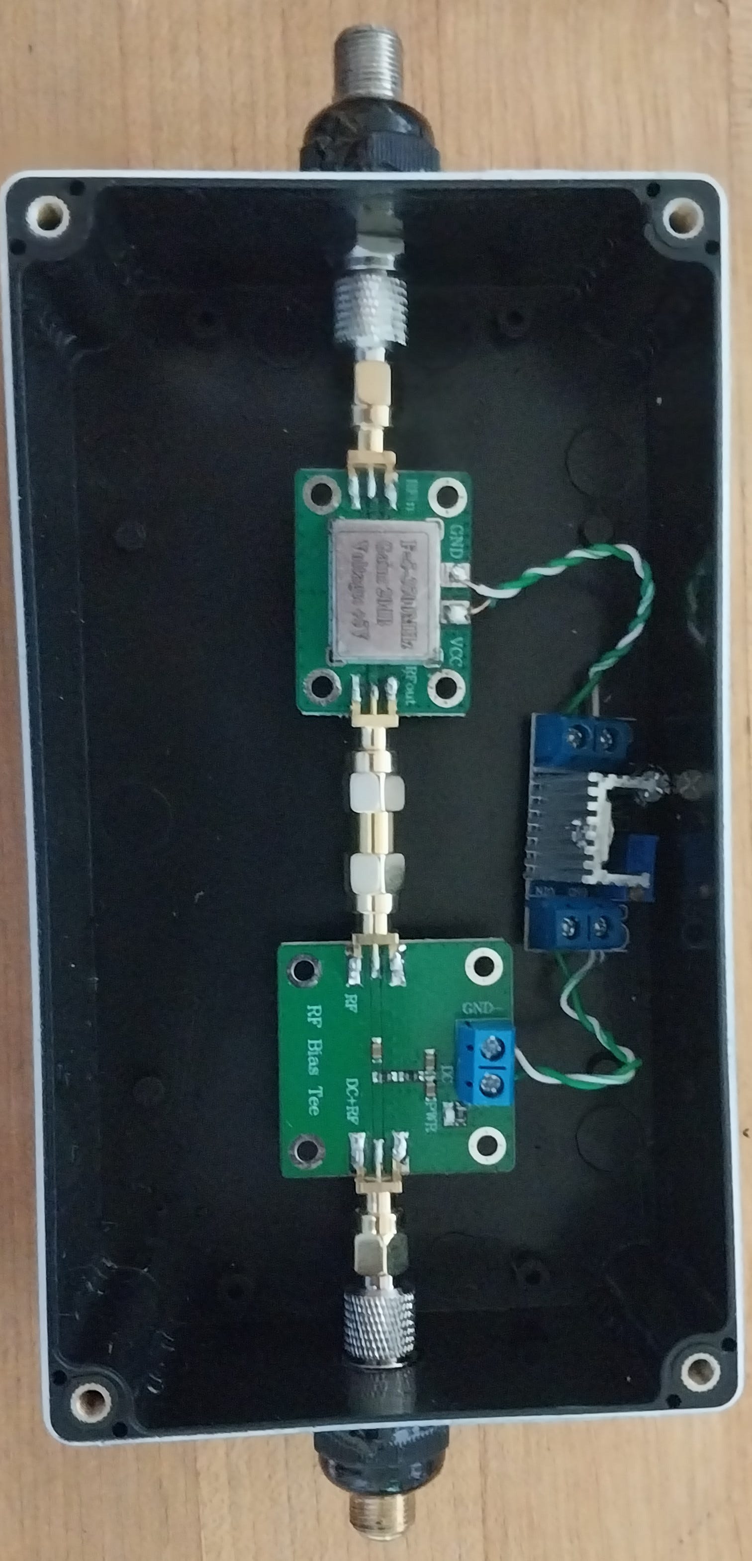
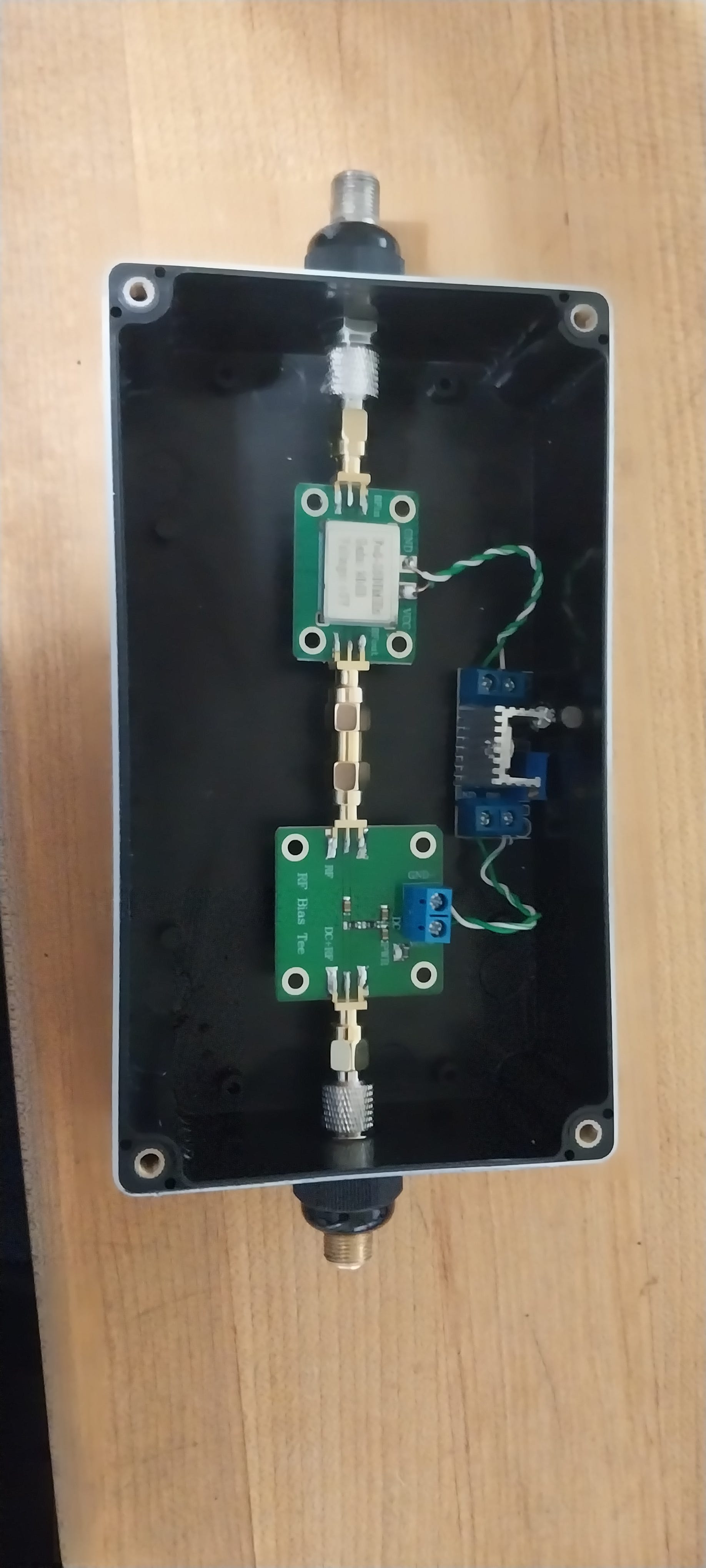
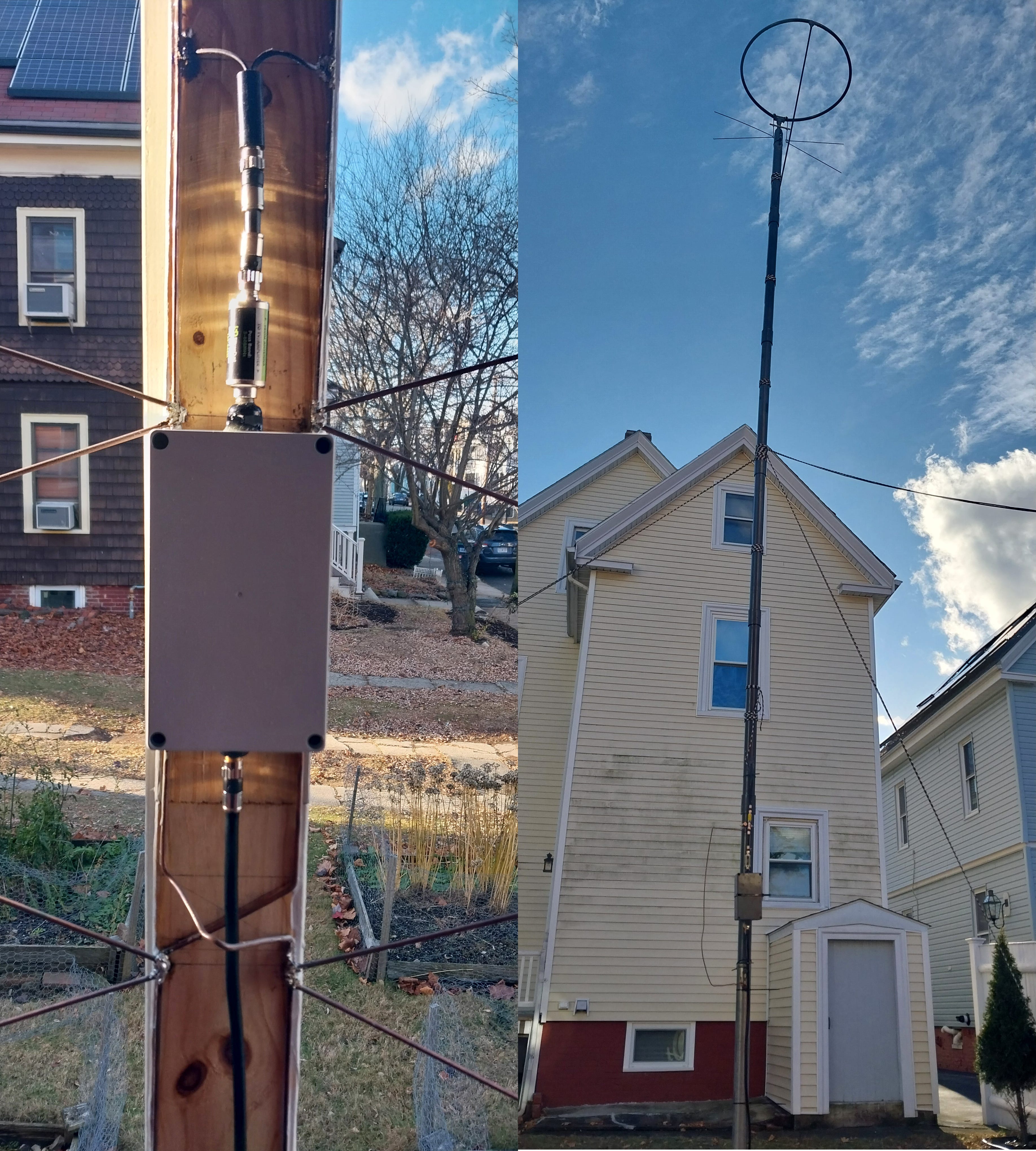
The outdoor homebrew preamplifier, above, can be configured to take any reasonable voltage over 6.5, and for about $75 you can build two of them from parts available on Amazon with free shipping.
I built a pair of them because my wife and I needed a couple of TV preamplifiers but were shocked by their prices. We also struggled to find a preamp that would accept the 12 volts direct current we could easily feed to our antenna sites.
(My wife and I use a Televés SmartKom to grab particular channels from distinct antennae placed in different spots and pointed in different directions. Around $200, it is a great value for us, serving as our distribution amplifier, antenna multiplexer and, now, power injector. But it will feed only 12 volts D.C. to the antennae, which few off-the-shelf preamplifiers accept. Though additional injectors were possible, we do not have a close-by power receptacle in the basement where our antenna feeds meet the SmartKom. The SmartKom itself is powered over coax by a single injector we keep upstairs.)
I recommend that this not be your first time using a soldering iron, multimeter, Krazy Glue, epoxy, etc. If any part of the build process is unfamiliar to you, seek experienced guidance. Lacking an R.F. background myself, I posted several questions to r/electronics and r/rfelectronics. I received significant aid, especially from u/Defiant_Homework4577 and u/thephoton. Any remaining design mistakes are mine and mine alone.
These steps may be modified for ham radio, Flight Aware, etc., by appropriately substituting the F connectors and size of the project box. In any such scenario, ensure the amplifier board and bias-tee specifications each include the frequency range(s) you need.
Please note: The internal components of this amplifier are 50-ohm impedance, not 75 ohms like RG-6 coax. This may cause issues for very weak TV signals coming down RG-6 to the preamplifier. The 50-ohm-impedance segment to the amplifier is under a tenth of a wavelength across TV’s frequency ranges, which should minimize any such issues for TV signals (we receive signals from 40 miles away with these amplifiers without issue). The output of the amplifier is also 50-ohm impedance, but due to the boost from the amplifier it is hard to imagine any digital-reception issue arising from reflection at the output side’s transition to 75-ohm RG-6. (I considered modifying a 4:1 balun to 6:1 to match our antennae to the 50-ohm amplifier input, but our pre-amplifier filters are 75 ohms anyway.)
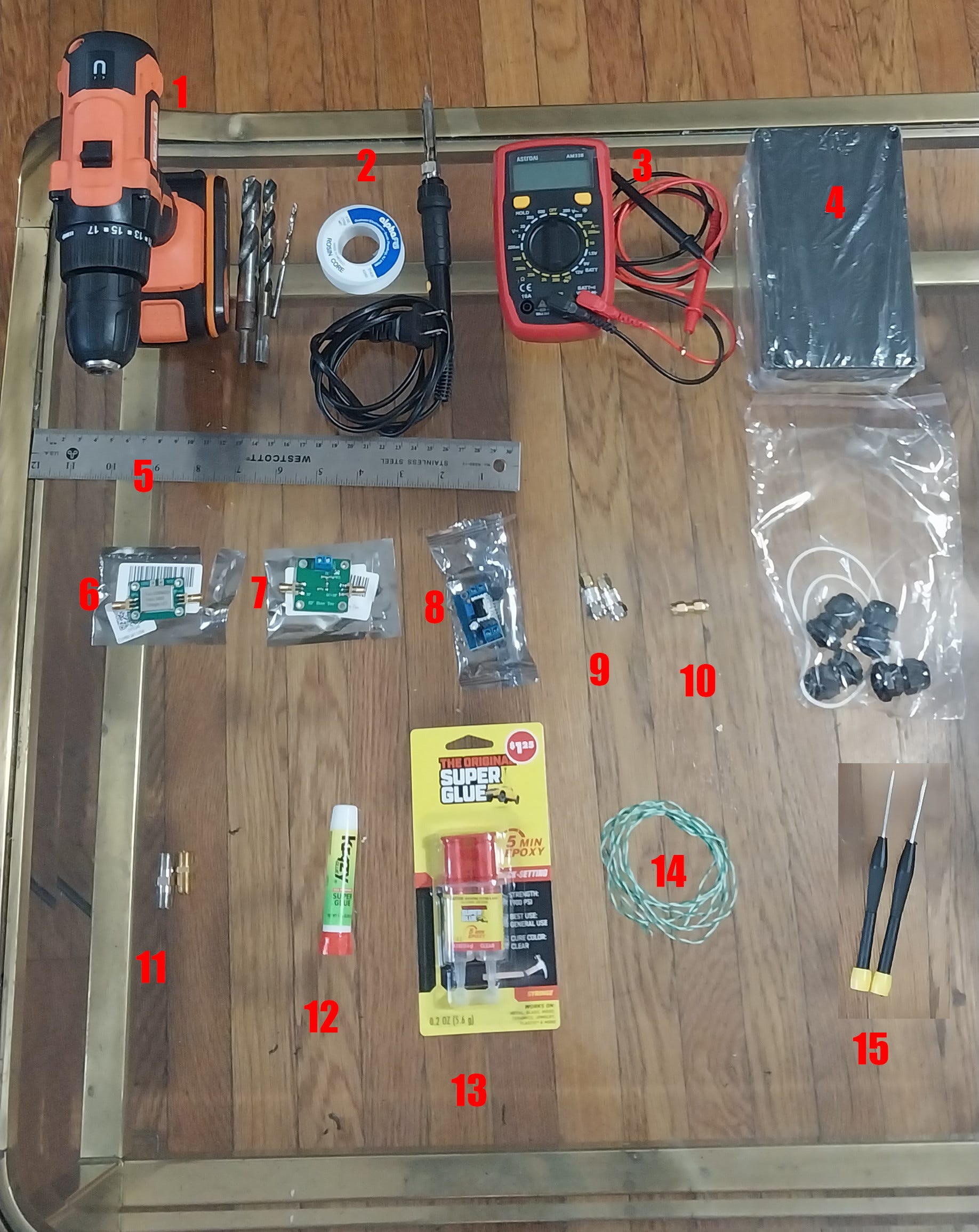
This build requires about an hour, not including drying times, and 15 things:
Drill and bits of progressive sizes up through a half inch (of course, you may also use a step drill bit, but we did not buy one solely for this project)
Soldering iron and solder
Multimeter (or at least a voltmeter)
Ruler
Female-to-female F-type connectors, preferably of varying sizes (We bought a five pack, here, but they were too short for everything to fit end-to-end in the project box. I was, however, able to use them to free up some longer ones we had elsewhere to use in our preamps.)
Krazy Glue or a similar product (available at Dollar General in my town)
Quick-setting epoxy (also available at Dollar General in my town)
Copper wire and a means of cutting and stripping it (I used wires from some spare CAT-6 cable, needle-nose pliers and a box cutter.)
Small flathead and Phillips screwdrivers
If you substitute any of the exact components specified, ensure everything will fit and play well together.
You may also need or wish to have—
Spray paint
Low-grit sandpaper
Additional shielding, or, if you know what you are doing, use a metal project box and adjust these steps accordingly.
If you need to build a power injector, too, you will need—
A wall wart of appropriate voltage (at least 1.5 volts higher than needed by the amplifier board) and sufficient know-how to connect it properly and safely
A second bias tee
A second, likely smaller, project box
Sufficient S.M.A.-to-F-type adapters
Coax and coax connectors
Here are the steps to build the preamplifier:
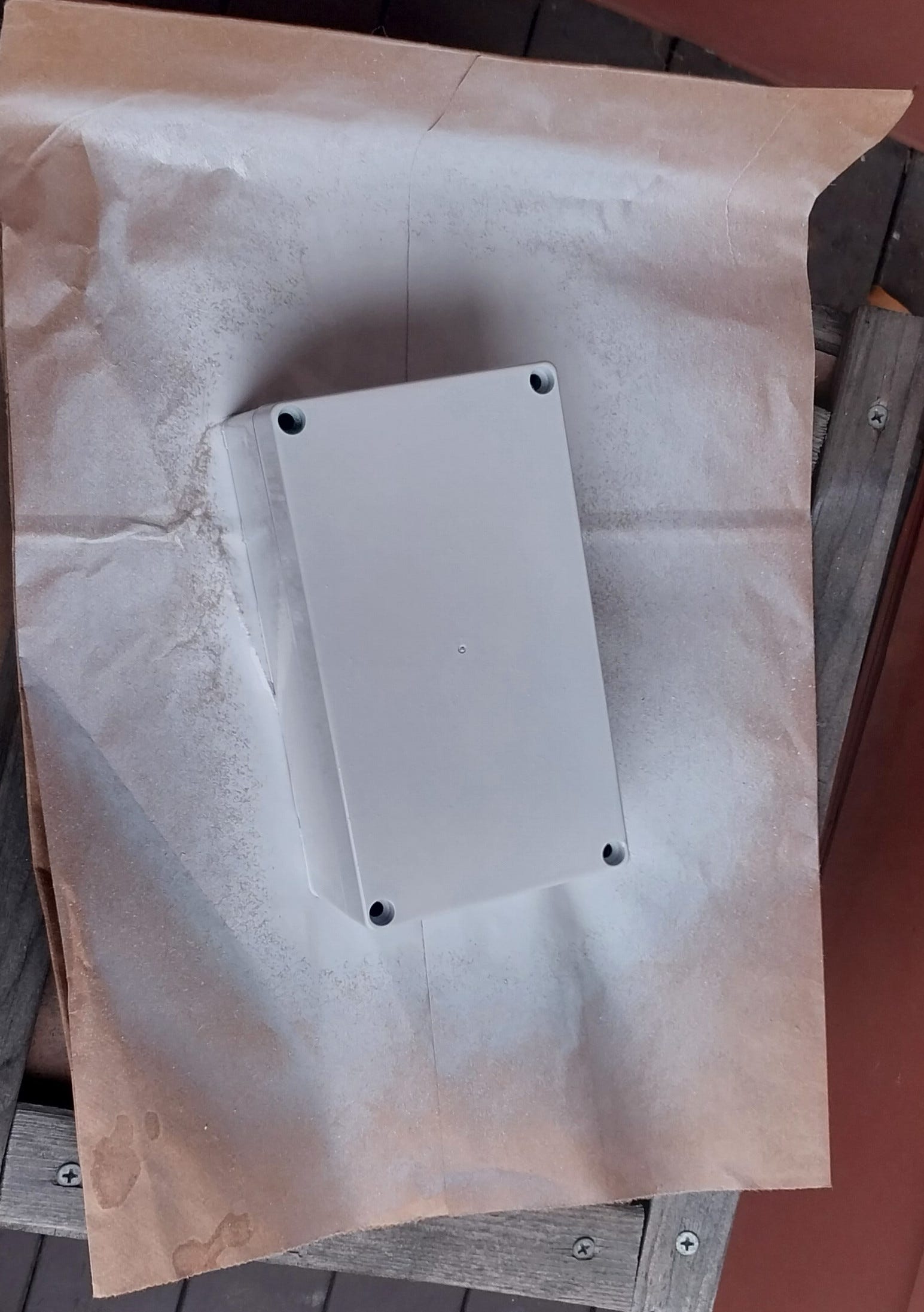
Prepare the project box.
Remove the plastic wrap from the project box and check the back of it. One of the project boxes we received had a sizeable bump that would have presented an issue for mounting it flatly. If present, sand off the bump.
(Optional) Take the box outside and spray paint it whatever color you need.

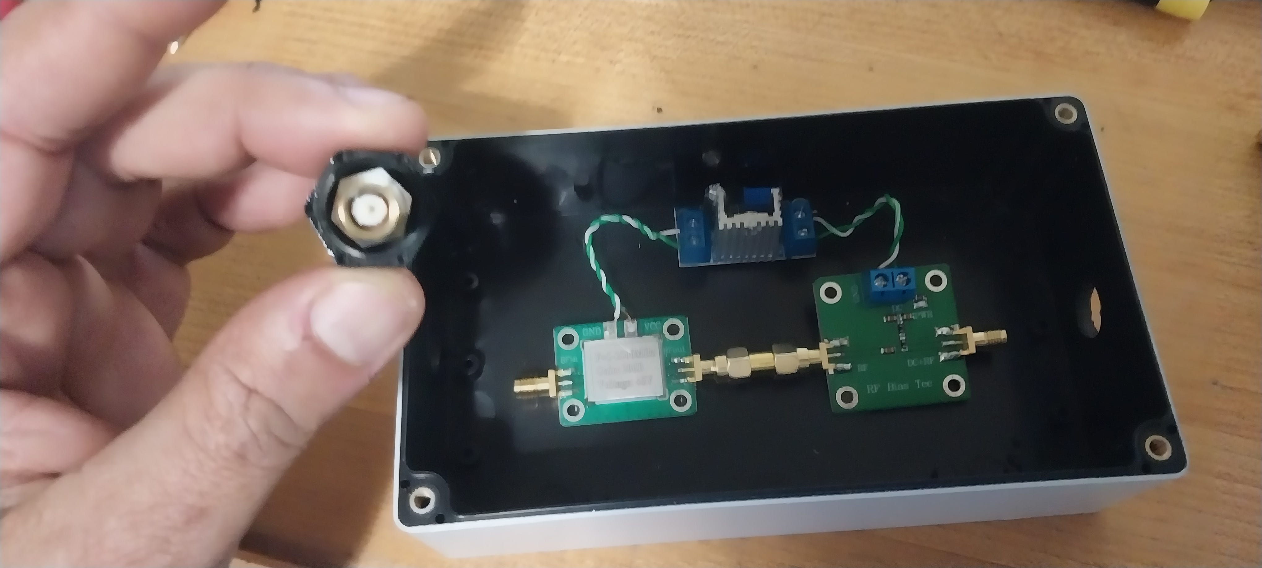
Adjust the regulator to feed the amplifier board.
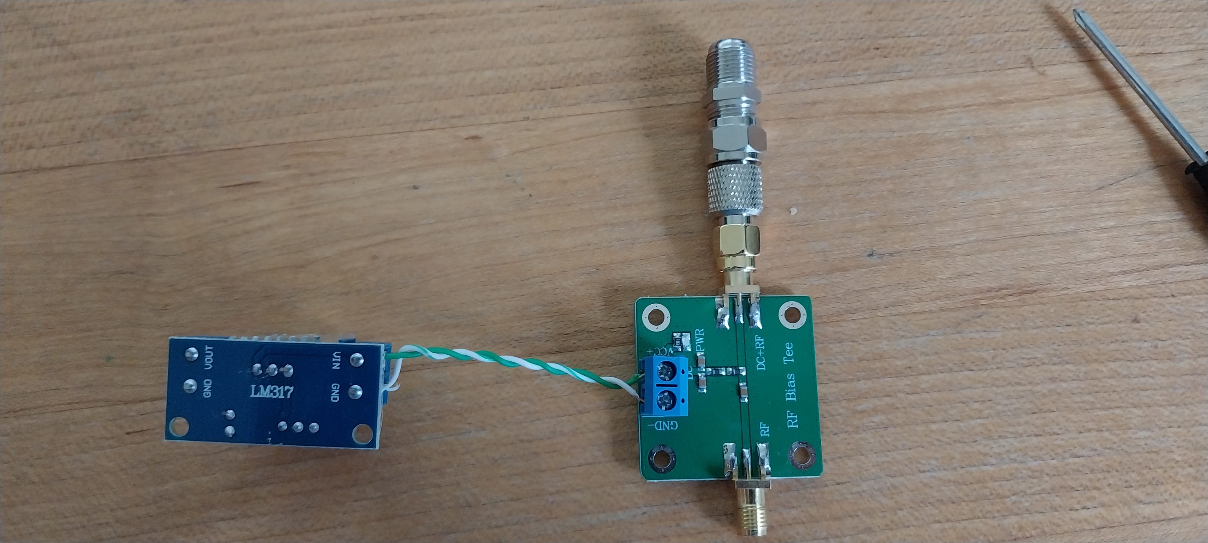
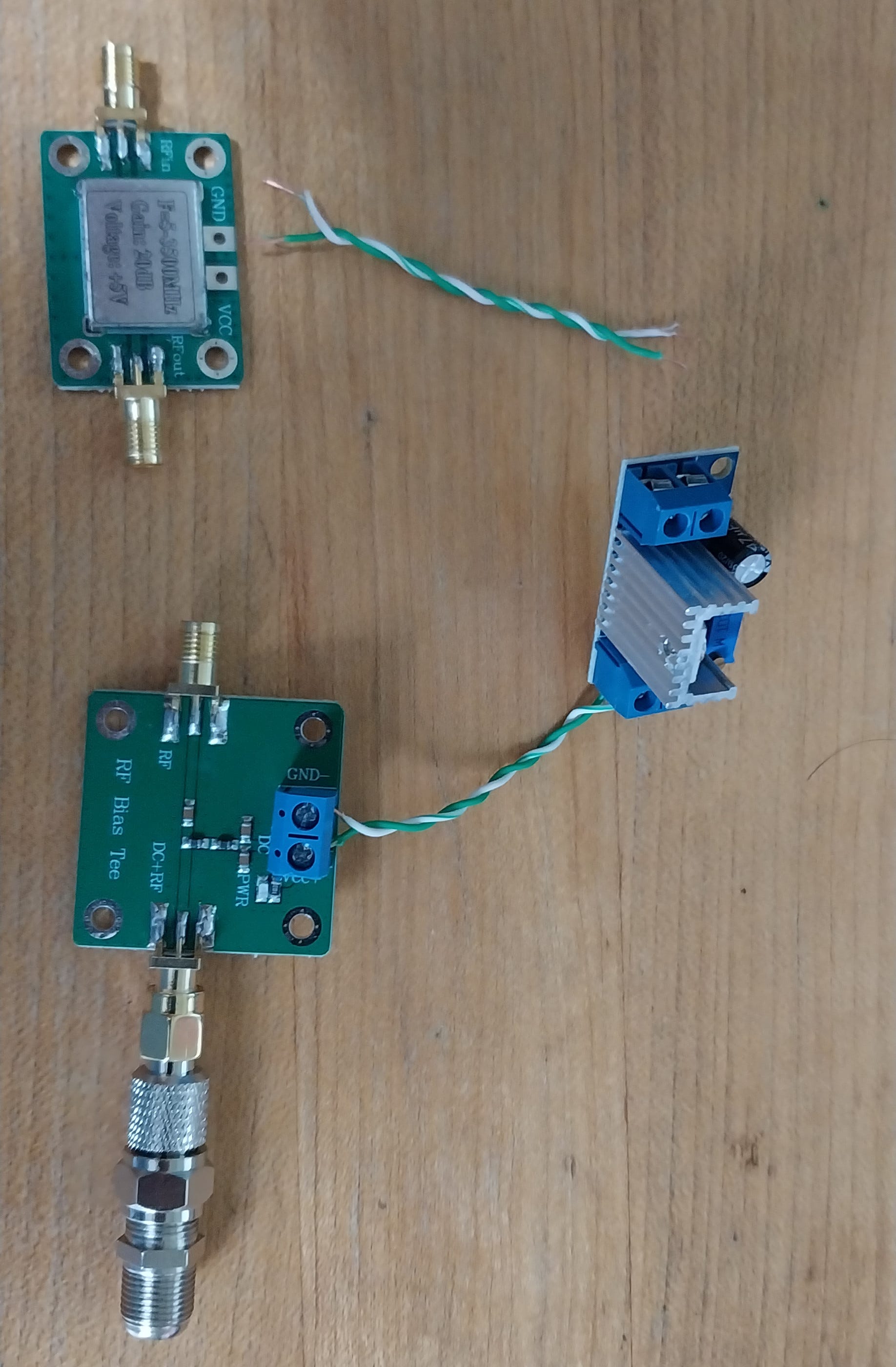
Unwrap the bias tee and regulator.
Connect one of the S.M.A.-to-F-type adapters to the “DC + RF” side of the bias tee.
To that, now connect one of the female-to-female F-type connectors.
Cut about two inches of two strands of copper wire and strip the ends.
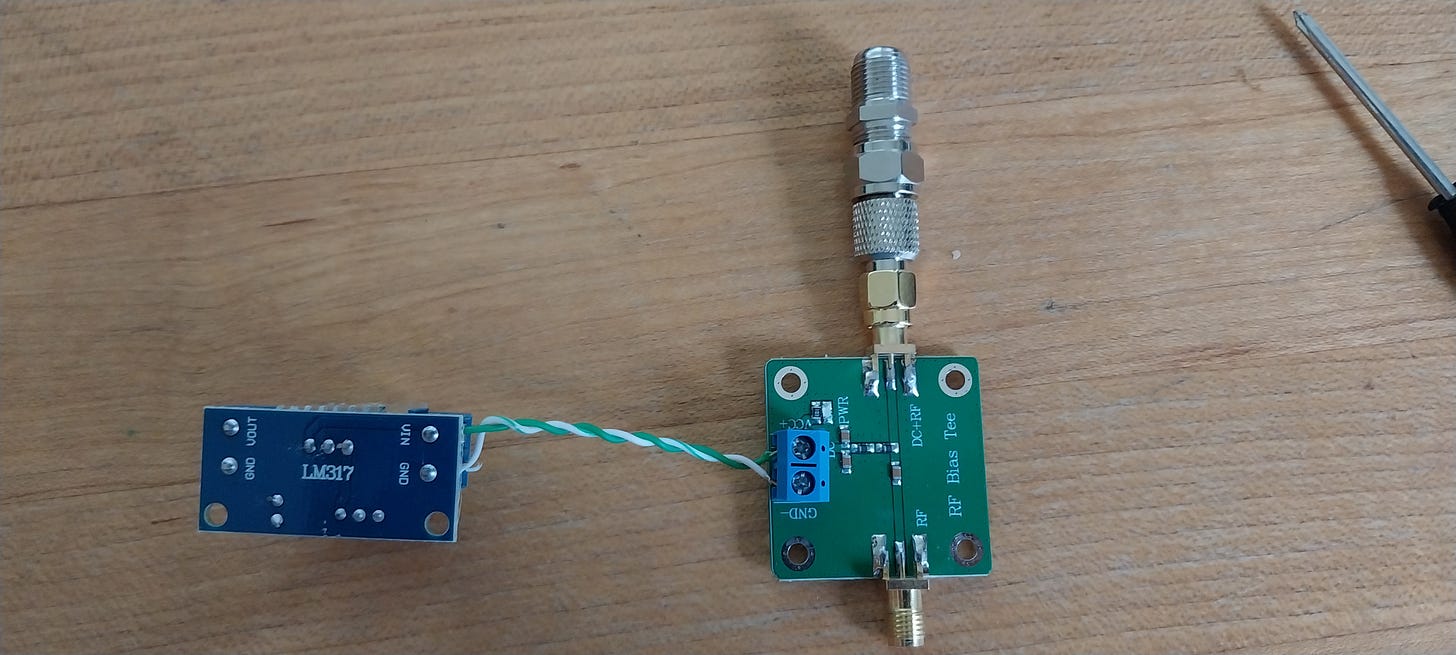
Use the wire and screw-terminals to connect the VCC+ terminal on the bias tee to the VIN terminal on the regulator and the GND- terminal on the bias tee to the corresponding GND terminal on the regulator.
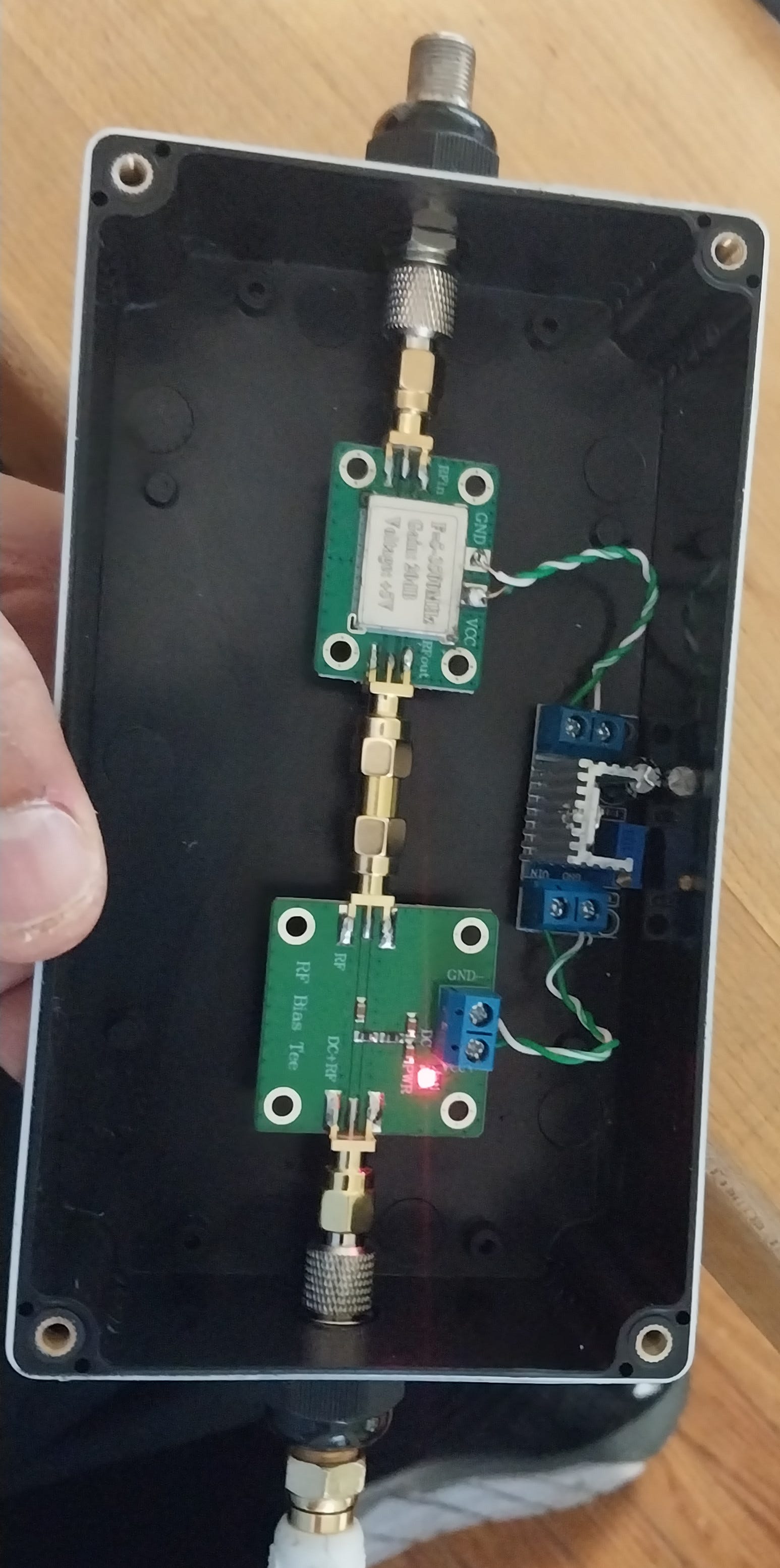
Plug the bias tee into a powered coax cable and ensure the red light illuminates. (If it does not, one of your connectors may be faulty. Your multimeter should show voltage across the outer shield and inner conductor of the coax feed, and the outside and inner conductor of the S.M.A.-to-F-type adapter.)
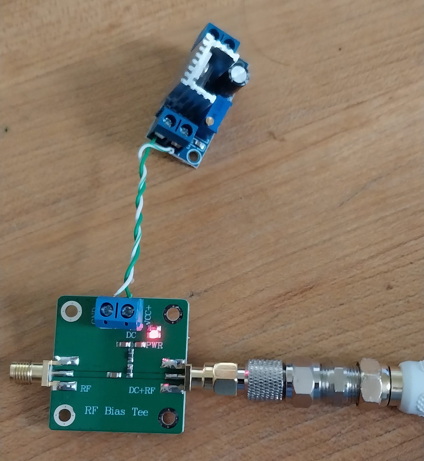
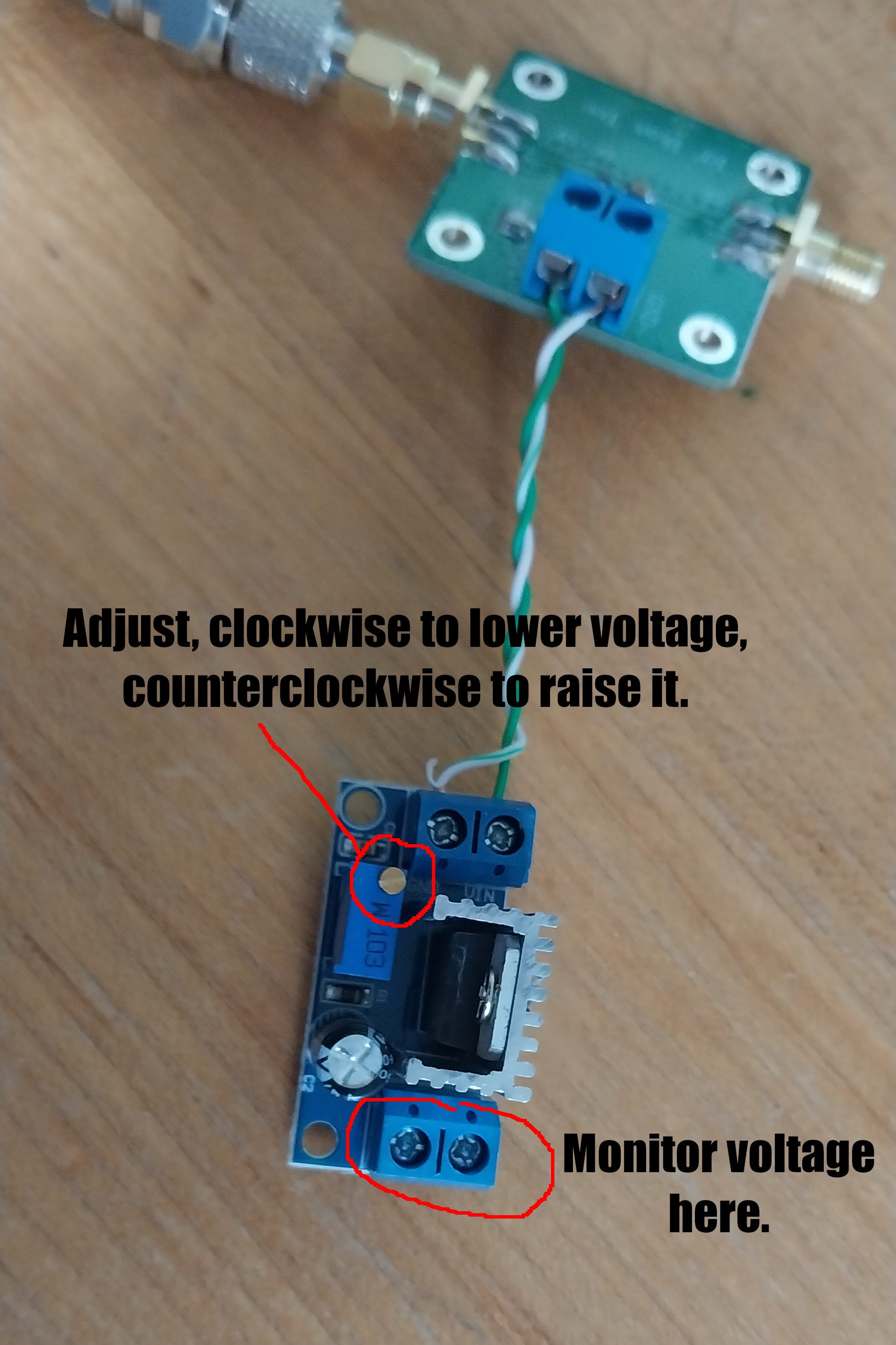
Use your multimeter to monitor the voltage on the output side of the regulator. Turn the flathead screw on the regulator clockwise until the output reaches five volts. No worries if you turn it too far, simply turn the screw counterclockwise to raise the voltage. For reliable performance, you need at least a 1.5-volt drop across the regulator.

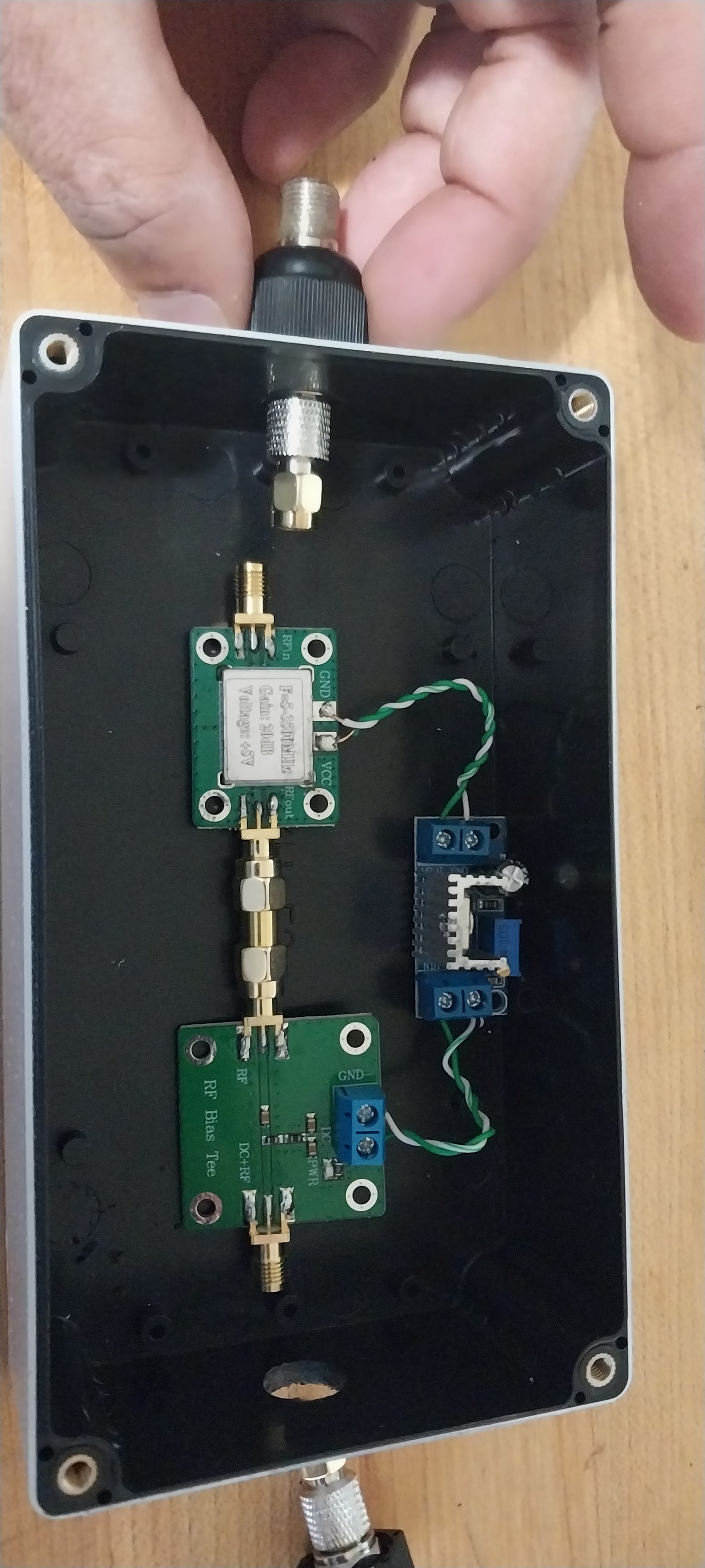
Connect the amplifier board.
Unwrap the amplifier board.
Cut another two inches or so of two copper wires and strip the ends.

Solder one copper wire each to the VCC and GND points on the amplifier board, being careful not to short across the VCC lead and the shielding.
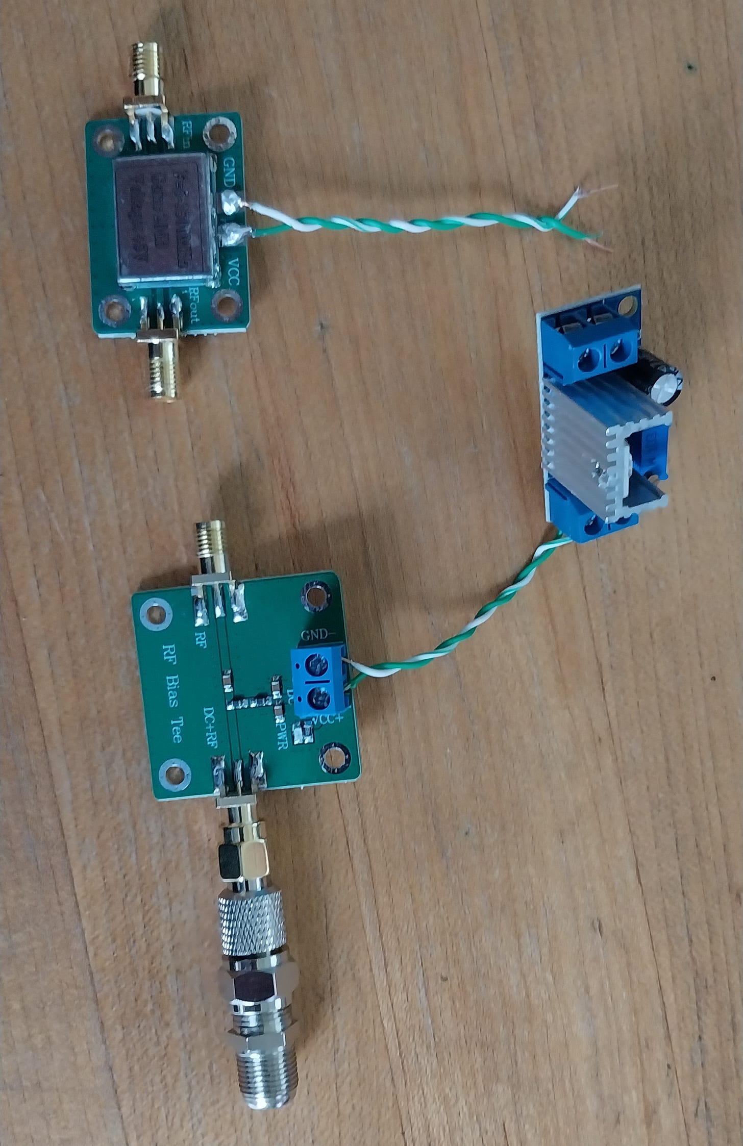
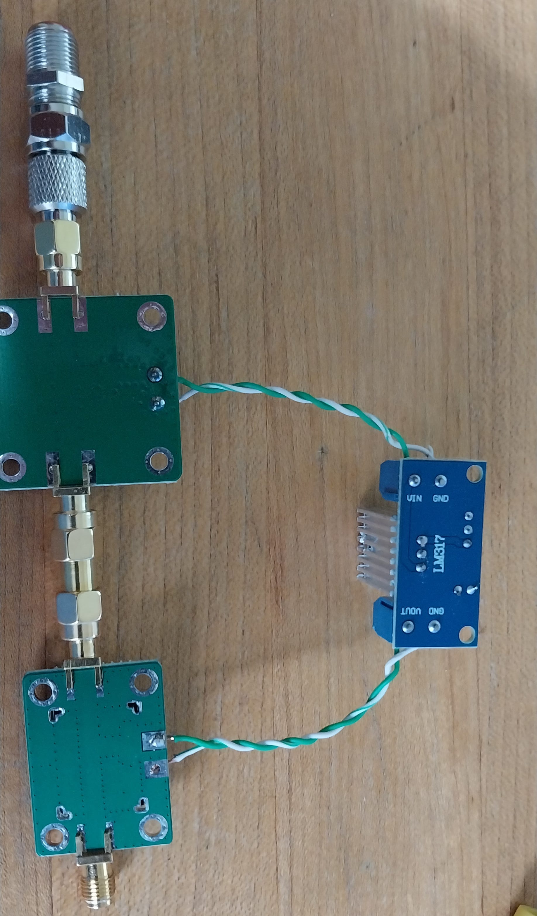
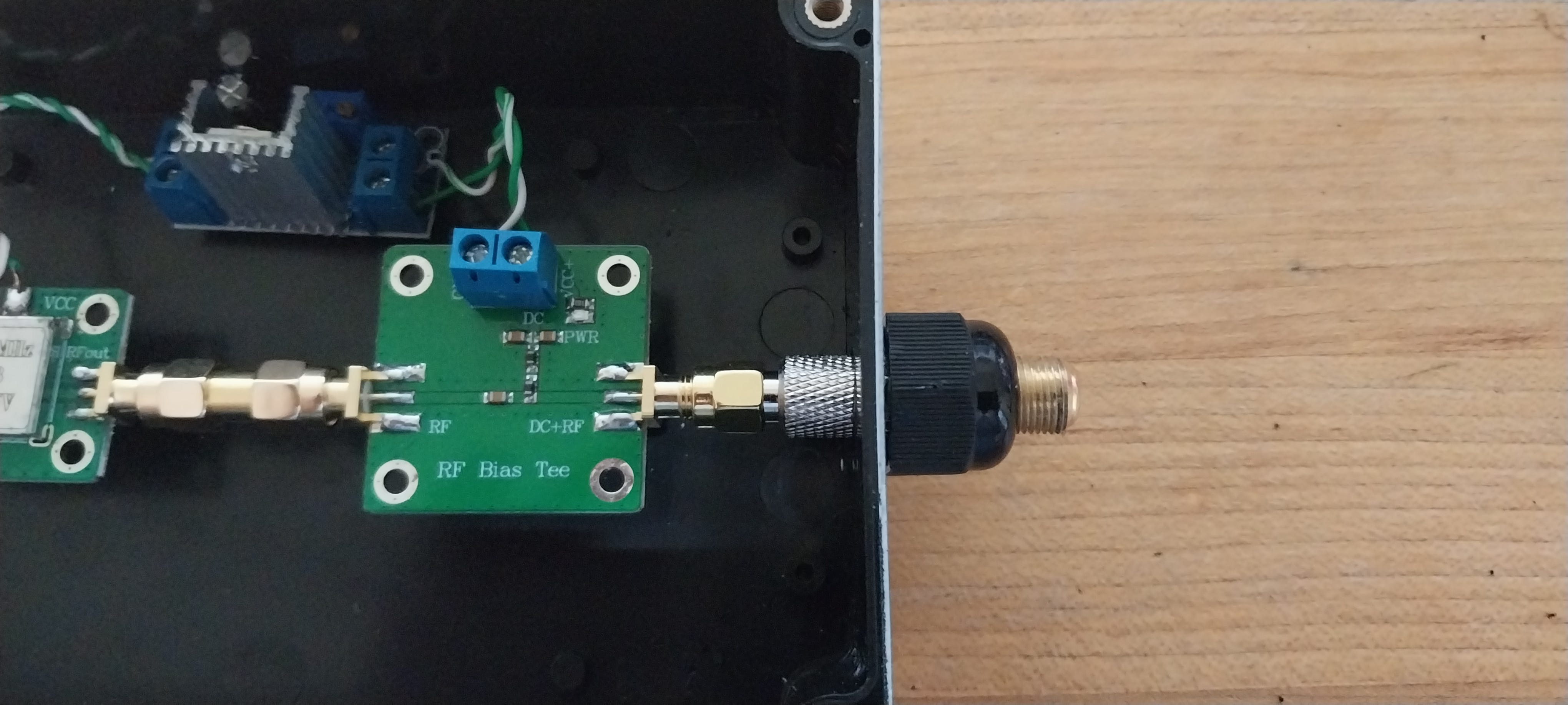
Connect the “RF out” side of the amplifier board to the “RF” side of the bias tee using the male-to-male S.M.A. connector.
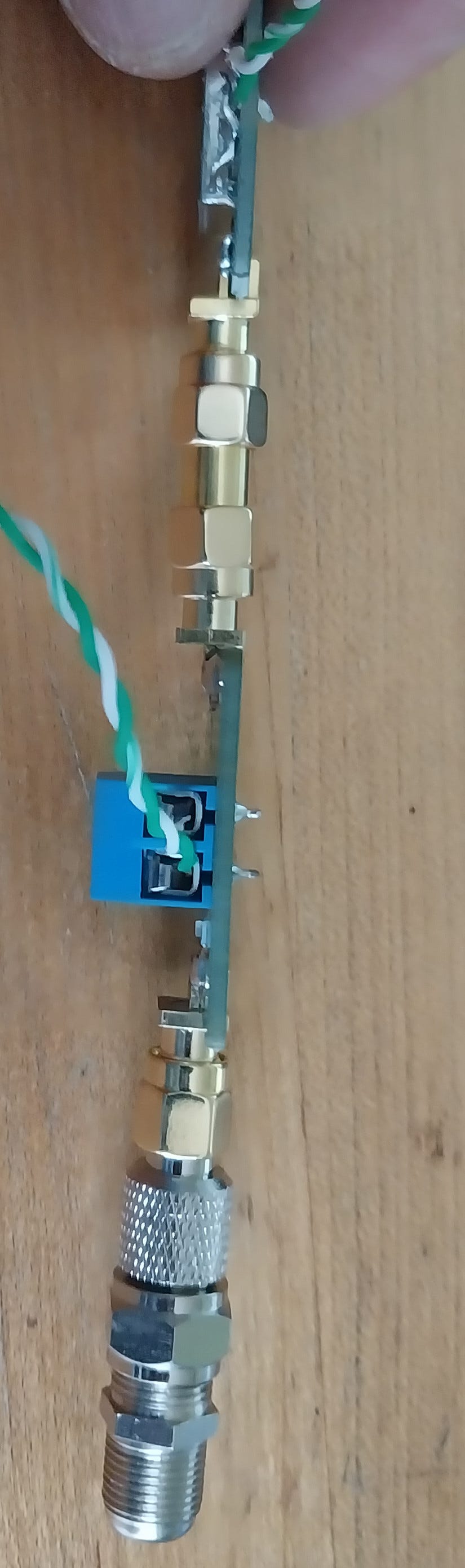
Make sure the bias tee and amplifier boards end up parallel to each other. This is important to avoid interference.
Secure the copper wires coming from the amplifier board into the screw terminals on the output side of the regulator, VOUT to VCC and GND to GND.

Prepare to mount the boards in the project box.
Plug the other male-to-male S.M.A.-to-F-type adapter into the “RF in” side of the amplifier board.
To that, connect another female-to-female F-type connector.
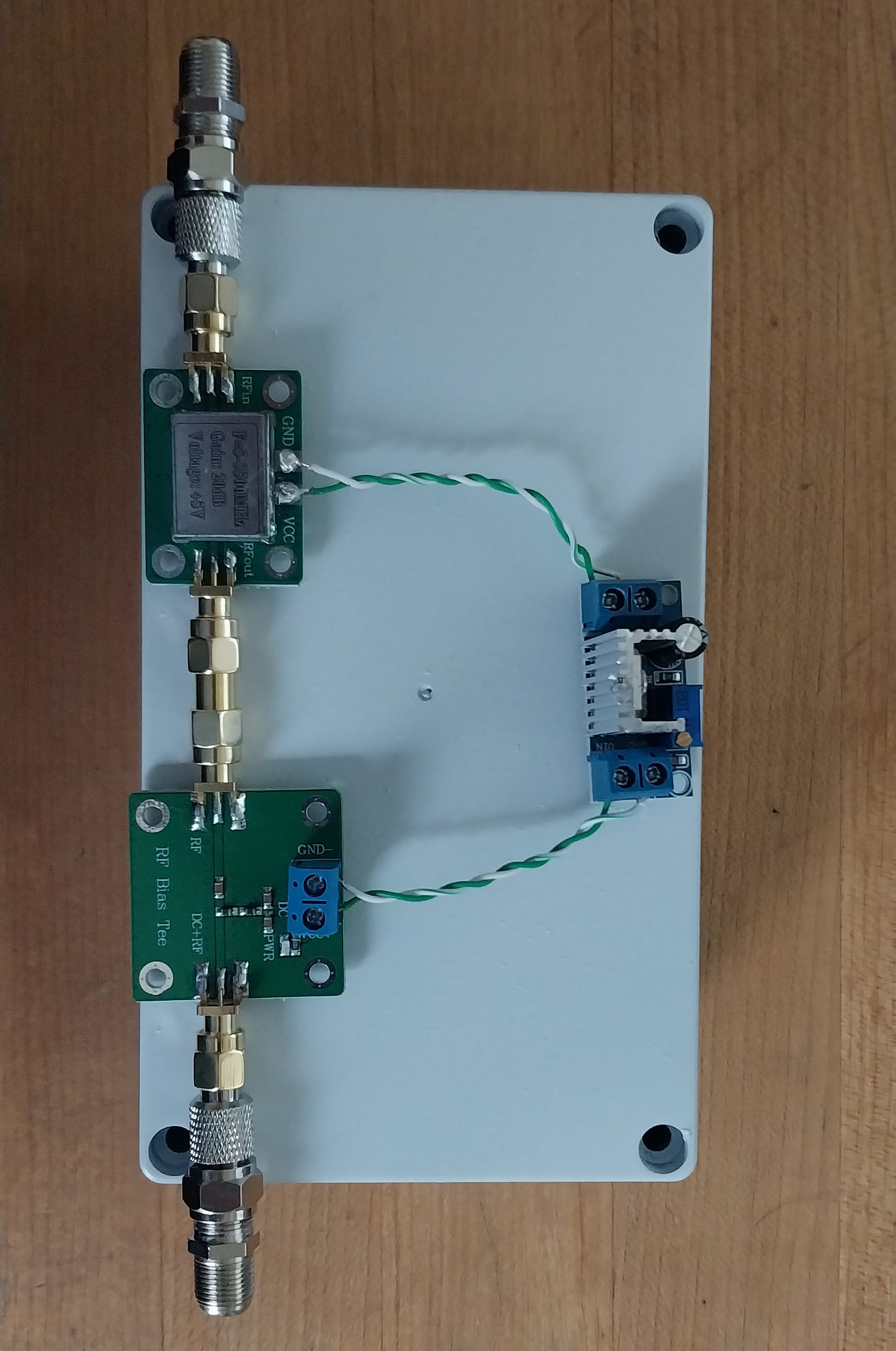
Lay the whole thing out on top of the project box to get an idea of the grommet placements. At this point, it became clear to me that the whole grommets would not fit, and I decided to use just the outermost part of them. In turn, this informed my decision of the size of the holes to drill in the next step.
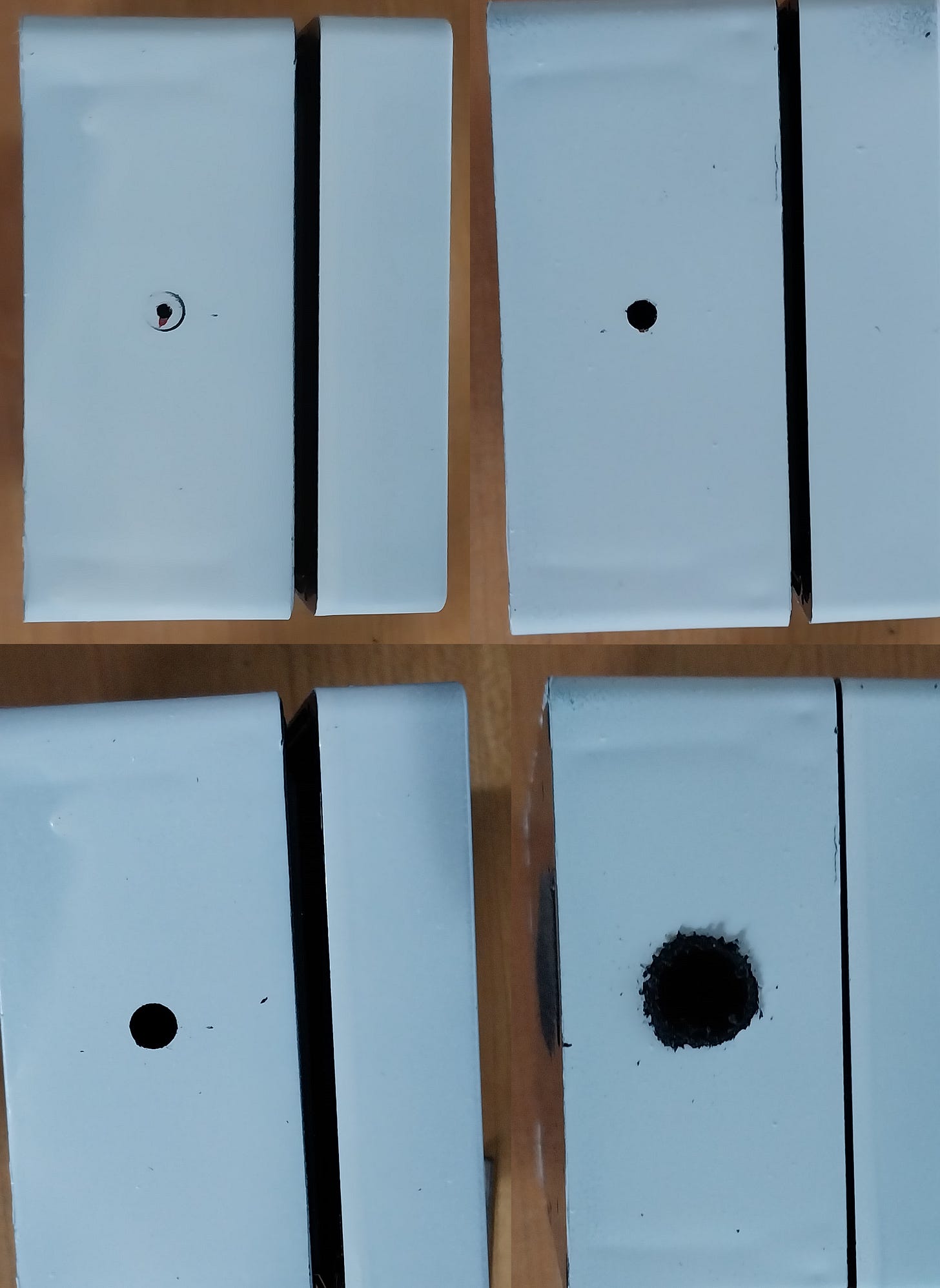
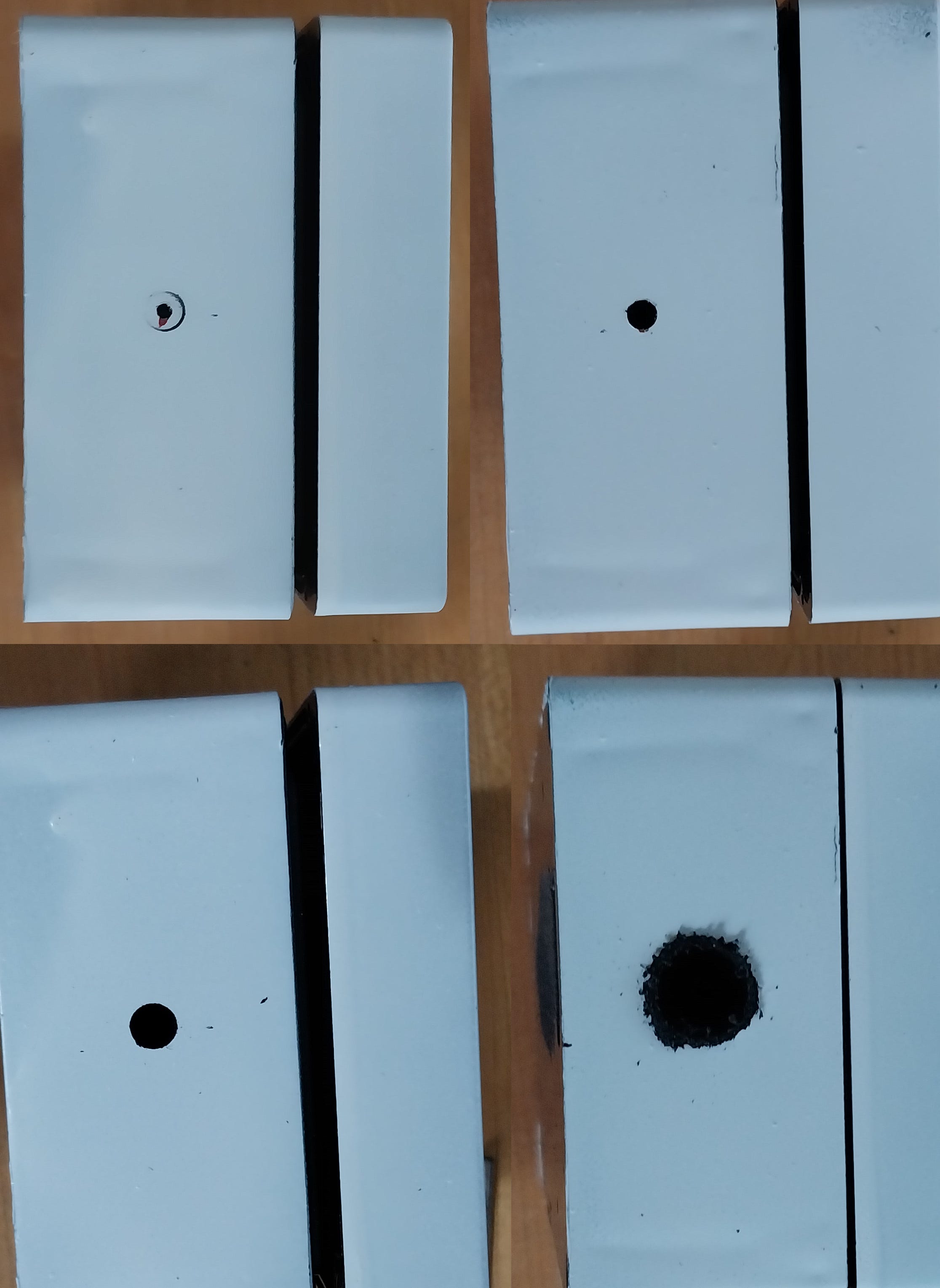
Drill the project box.
Measure and find the center, or whatever point you need, of both sides of the project box.
Either use a step drill bit or drill progressively larger holes until you have reached a half inch.
Finalize your choice of female-to-female F-type connectors and set everything in the project box.
Disconnect the S.M.A. sides of the S.M.A.-to-F-type adapters from the boards and place the boards in the project box.
Experiment with different female-to-female F-type connectors and the outermost part of the grommets to find a combination that will fit snugly. If necessary, sand the wide part of the grommet to achieve a good fit.

Without letting the boards rotate, plug back in the powered coax and check that the red light still illuminates and you do not have any shorts. You may wish to check the current flow through the amplifier board. It should pull about 90 milliamps.

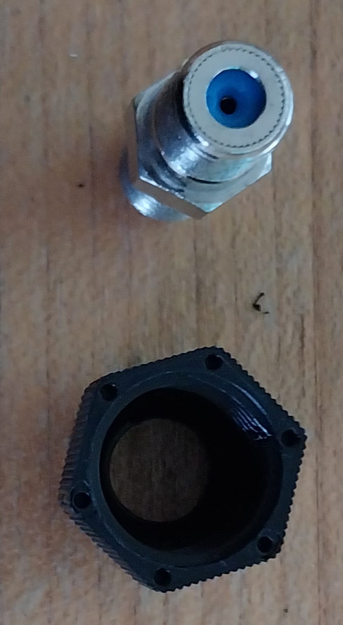
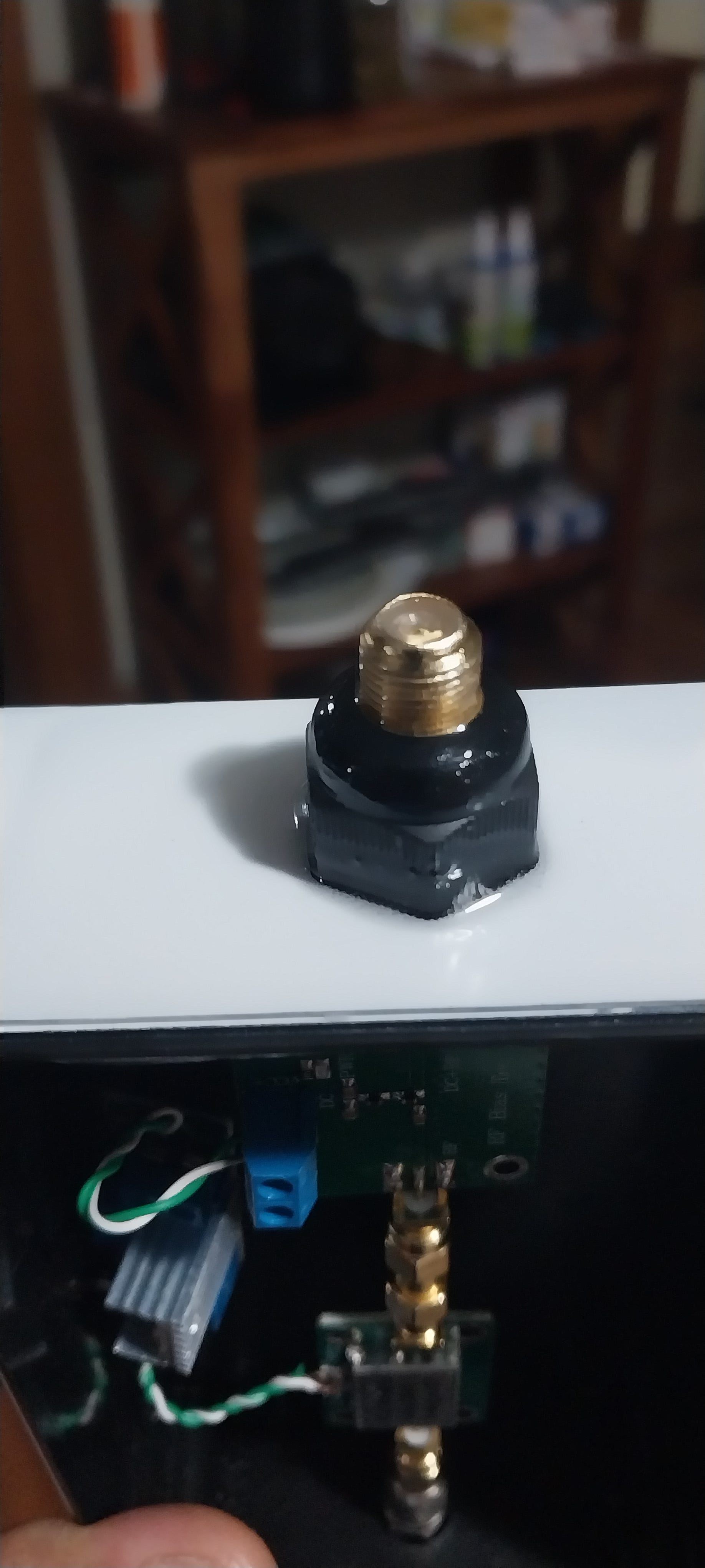
Attach each grommet in two stages.
Disconnect the male-to-male S.M.A-to-F-type adapters from the circuit boards.
Disconnect the female-to-female F-type connectors from the adapters.
Lay out the female-to-female F-type connectors and the grommets.

Be careful—Krazy Glue bonds to skin instantly. Strongly consider wearing gloves. Place small drops of Krazy Glue at the bottom of the inside of one of the grommets and seat a female-to-female F-type connector inside it. Make sure it is flush and straight. The Krazy Glue should hold the two pieces securely, but the epoxy that comes later will reinforce it.
Repeat with the other grommet.
Reconnect the male-S.M.A.-to-male-F-type adapters to the female-to-female F-type connectors. Again, make sure everything is flush and straight.
Place a few drops of Krazy Glue on the edge of the grommet where it will meet the project box.

Reconnect the male-S.M.A.-to-male-F-type adapter, through the project box, to one of the boards. Again, make sure all is flush and straight. The glue should hold the grommet on the box securely and stop it from rotating. The epoxy that comes later will reinforce it.

Repeat with the other side.
Mix some epoxy.
Use the epoxy to seal 1) where the grommets meet the project box and 2) where the coax connectors protrude from the grommets. The goals of the epoxy are 1) to reinforce the Krazy Glue and 2) to create weathertight seals. Ensure the epoxy does not meaningfully interfere with the threading on the coax connectors. Ruthlessly clean any excess epoxy with a moist paper towel before it dries. Wash your hands before any stray epoxy dries on them.

Let everything dry.
Label the input and output sides of the project box to ensure you connect the finished product properly.
You may then close the project box. Make sure to turn the screws snuggly without breaking anything.
Take the amplifier to its final location and test it.
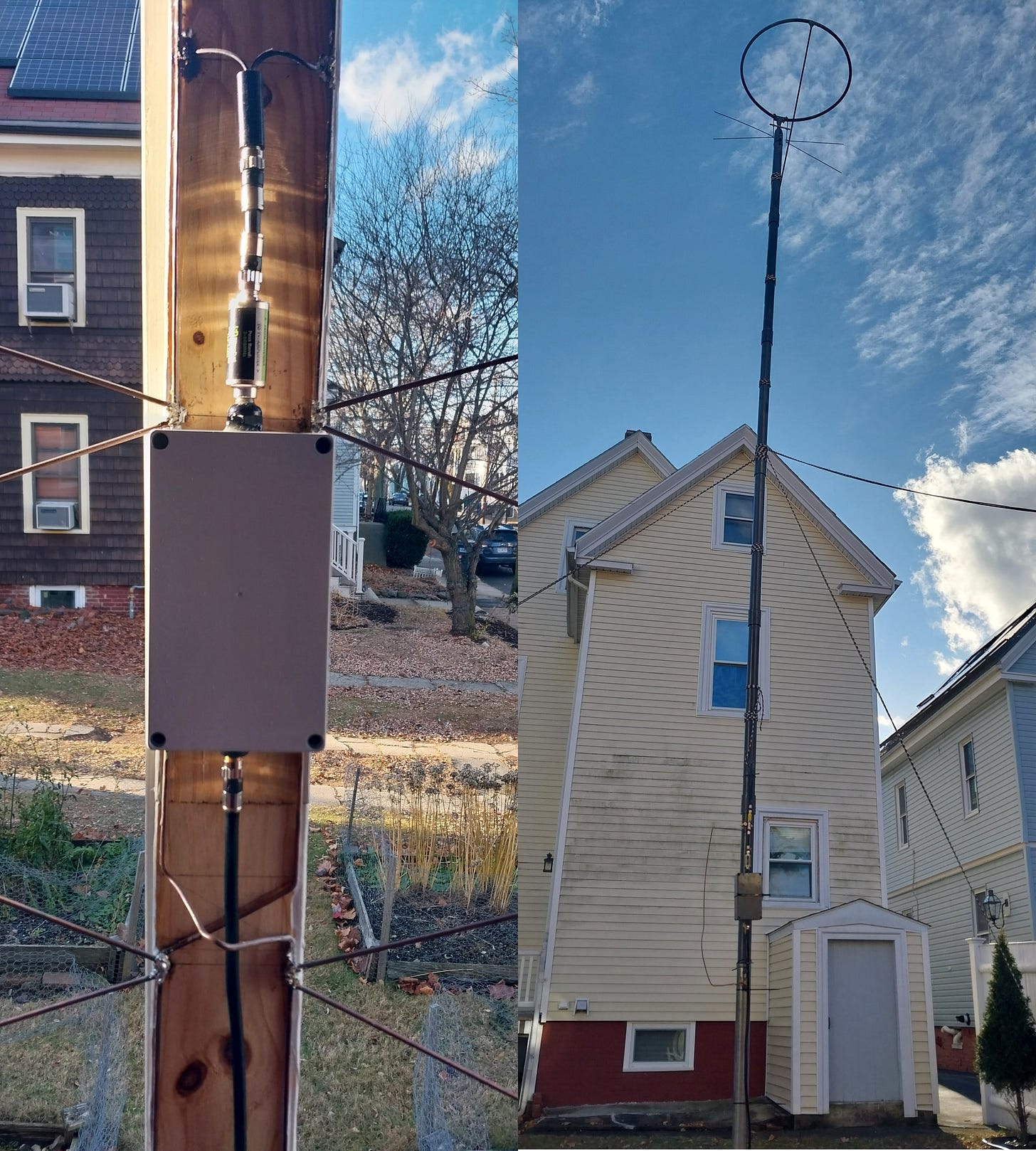
If you get glitchy interference, open the box to ensure the boards remain parallel. If you have placed the amplifier near likely interference, you may need to place additional shielding in or around the box. If this is your first time connecting an amplifier to a particular TV antenna, it is distinctly possible you also need an up-to-date 5G filter connected before the amplifier, as pictured above.


I offer this post for educational purposes without any warranty of any kind, express or implied. This post contains no affiliate links and no one mentioned herein profits from the purchases of any of the required equipment. By attempting this build, you agree to indemnify and hold harmless myself and all others mentioned herein from any and all liability. Do not shake hands with your soldering iron or Krazy Glue yourself to yourself.